SLM21-HPEF2 Safety Door Switch(6 contacts), 3NC+1NC/1NO
82 Items sold in last 12 months
3 People watching this product now!
SKU: SLM21-HPEF2 Category: SLM21 Safety Door Switch(6 contacts) Tag: Safety Door Switch 3NC+1NC/1NO Brand: ESPE
Product Feature:
- Multiple contacts for selection;
- Holding force 1300N;
- Ip67 protection rate;
- Various inserting direction;
- Support general load or micro-load.
Specification
- Magnetic voltage/indicator: Electromagnetic DC24V Green LED
- Locking mode: Power to lock
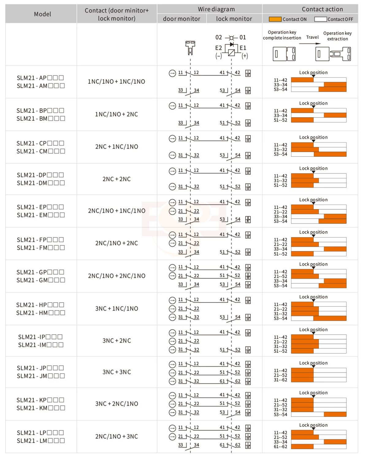
- Contact type: 3NC+1NC/1NO
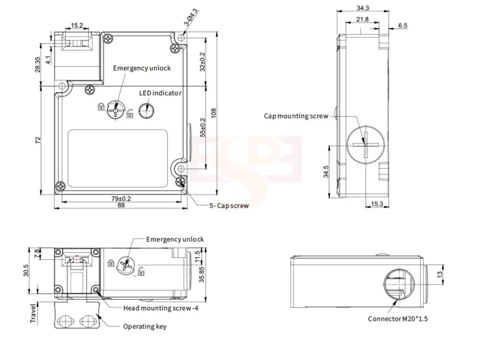
- Connector size: M20
- Head direction Material: Plastic
- Key insertin direction: Front
| Electromagnetic tube | |
| Rated Voltage | DC24V |
| Capacity | 4.8W |
| Rated current | Approximate 200mA |
| Insulation | Clas N (130°C) |
| LED indicator | LED indicator |
| Rated voltage | DC24V |
| Rated current | Approximate 1mA |
| Luminous color (LED) | Green |
| Safety level | Safety level |
| Certificate | CE TUV |
| Standard | EN60947-5-1, GB14048.5, IEC61508, EN ISO 14119 |
| Protection rate | IP67 |
| Material | PA66 fire retardant |
| Mechanical lifespan | >1 million |
| Electrical lifespan | Over 150, 000 times (AC240V3A, resistive load) |
| Using Type | AC-15 |
| Rated operating voltage(Ue) | 240V |
| Rated operating current(Ie) | 3A |
| Electrical parameter | |
| Contact resistance | <24mΩ |
| Nominal discharge current (lth) | 10A |
| Rated insulation voltage (Ui) | 300V |
| Anti-electric shock level | Class II (double insulation) |
| Pulse withstand voltage (EN60947-5-1) | 2.5kv |
| Insulation resistance | >100mΩ |
| Short-circuit protection | 10A, 250V requires a quick-break fuse |
| Vibration resistance | 10-55HZ, double amplitude 1.5mm |
| Compact resistance | Durability 1000/S², mal-operation 300m/S² |
| Conditional short-circuit current | 100A (EN60947-5-1) |
| Space of contact | Above 2 x 2mm |
| Action characteristic | |
| Direct opening force | Minimum 60N |
| Direct opening travel | Over 10mm |
| Allowed operating speed | 0.1m-0.5m/s |
| Allowed operating frequency | Maximum 30 times/minute |
| Holding force | 1300N |
| Environment | |
| Operating environment | 3 (EN60947-5-1) |
| Operating temperature | -10°C to 55°C ( no freezing) |
| Operating humidity | <95% RH |
Below wire diagram for switch with key inserts & lock status. (Terminal 12 &41, 22&51, 32&61 is inside connection)
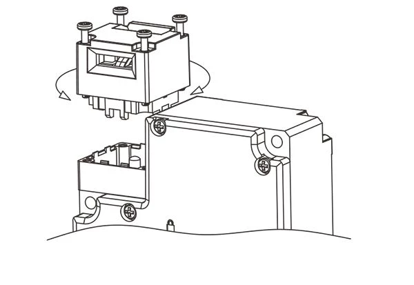
Releasing the 4 screws on top of the cap, spinning the direction of top cap until the suitable position for key inserting
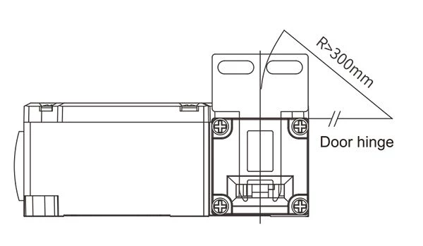
When install on side hung door, it should be over than semidiameter.
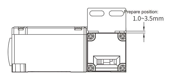
Please install the safety switch door and insertion key under range 1-3.5mm.
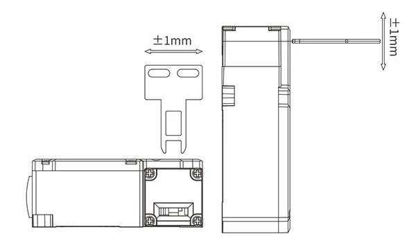
The installation of operation key allows ±1mm error within the key insertion center of the hole.